|
|
Data- Telecom Equipment |
|
|
About Us |
|
?2001
American Tele Data |
|
ICC
Raceway- ICC Raceway Systems- Raceway System Solutions-Cable Tray
Systems-SnakeTray Supplier- Cable Tray Supplier- Cable Tray Distributor-
Cable Tray System-Raceway Systems- Flextray- BasketTray
 
    Sample
Raceway Systems Sample
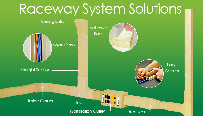
Raceway Systems

American Tele Data carries ICC's entire raceway system product line.ICC's new Elite Multi-Media Box has four separate knockouts for raceway system fittings and features rear access for cable entrance. ICC junction boxes allow easy cable access entry, contain cable routing posts for added stability, and are designed with raceway knockouts. All knockouts can be easily removed with pliers to accommodate all ICC raceway sizes.
 Made of 94V-0 rigid vinyl for low voltage (under 50V) communication cabling, the raceway is easy to cut, trim and can be painted in order to create a custom look.All components of the Raceway System are designed to maintain a minimum 1 inch bend radius for both copper (making it Category 5, 5e and 6 compliant) and fiber optic cable. Raceways can incorporate a wide variety of media, including UTP, STP, ScTP, Coaxial, Audio, Video and Fiber Optic. ICC's raceways utilize a one-piece adhesive back design with an integrated latching system for quick changes and ease of installation. Made of 94V-0 rigid vinyl for low voltage (under 50V) communication cabling, the raceway is easy to cut, trim and can be painted in order to create a custom look.All components of the Raceway System are designed to maintain a minimum 1 inch bend radius for both copper (making it Category 5, 5e and 6 compliant) and fiber optic cable. Raceways can incorporate a wide variety of media, including UTP, STP, ScTP, Coaxial, Audio, Video and Fiber Optic. ICC's raceways utilize a one-piece adhesive back design with an integrated latching system for quick changes and ease of installation.
manufacturer's
including our new Snake Tray raceway systems, plastic raceway systems
and metal raceway system solutions, and cable trays featured above such
as Cable Manager cable tray, and Cablofil raceway, cable tray and raceway
systems, Hendry raceway , Newton, DEK raceways, ICC standard raceways,
and ICC's custom Raceway System Solutions (RSS). Designed to make installation
simple and easy, Cablofil wire cable tray is truly a revolutionary advancement
in cable management. Per the National Electrical Code, a cable tray
system is "a unit or assembly of units or sections and associated
fittings forming a rigid structural system used to securely fasten or
support cables and raceways. American Tele Data offers raceway system
solutions and cable tray systems from several manufacturer's including
our new Snake Tray raceway systems and cable trays featured above, Cable
Manager cable tray, and Cablofil raceway, cable tray and raceway systems,
Hendry raceway , Newton, DEK raceways, ICC standard raceways, and ICC's
custom Raceway System Solutions ICC's raceway structured cabling solutions
offer flexibility and ease of installation. Each component is skillfully
engineered and crafted to provide a clean and secure system that fits
virtually any open architectural environment. See all our raceway solutions
below.
 West Coast (866) FIBER-21 --(866) 342-3721- East Coast (866) 650-3282 West Coast (866) FIBER-21 --(866) 342-3721- East Coast (866) 650-3282
|
| |
ITEM NUMBER |
 |
DESCRIPTION |
|
Raceway 3/4”, 1-1/4”
and 1-3/4” Widths Raceway - Cable
Tray |
|
ICRW11SRxx*
ICRW11SR
|
|
Raceway, 3/4” W x .534” H, 6-ft. length |
|
ICRW12SRxx*
ICRW12SR |
|
Raceway, 1 1/4” W x .783” H, 6-ft. length |
|
ICRW13SRxx*
ICRW13SR |
|
Raceway, 1 3/4” W x 1.033” H, 6-ft. length |
 |
ICRW118Rxx
ICRW118R |
|
Raceway, 3/4" W x 1/2" H, 8-ft. length |
| |
ICRW128Rxx
ICRW128R
|
|
Raceway, 1 1/4" W x 3/4" H, 8-ft. length |
| |
ICRW138Rxx
ICRW138R |
|
Raceway, 1 3/4" W x 1" H, 8-ft. length |
|
|
|
Standard packaging 20 pcs./box. |
|
|
|
|
|
 |
|
Flat Elbow 90° Raceway - Cable Tray |
|
ICRW11EOxx*
ICRW11EO |
|
3/4” Flat Elbow 90o, 10 pcs./bag |
|
ICRW12EOxx*
ICRW12EO |
|
1 1/4” Flat Elbow 90 o, 10 pcs./bag |
|
ICRW13EOxx*
ICRW13EO |
|
1 3/4” Flat Elbow 90 o, 10 pcs./bag |
|
|
|
|
|
 |
|
 |
|
 |
|
Tee
& Base-Raceway - Cable Tray |
|
ICRW11TBxx*
ICRW11TB |
|
3/4” Tee & Base, 10 sets/bag |
|
ICRW12TBxx*
ICRW12TB |
|
1 1/4” Tee & Base, 10 sets/bag |
|
ICRW13TBxx* |
|
1 3/4” Tee & Base, 10 sets/bag |
| |
|
|
|
|
 |
|
 |
|
 |
|
 |
|
 |
|
 |
|
 |
|
|
 ICC
Raceway ICC
Raceway
All
components of the Raceway System are designed to maintain a minimum
1 inch bend radius for both copper (making it Category 5, 5e and 6 compliant)
and fiber optic cable. Raceways can incorporate a wide variety of media,
including UTP, STP, ScTP, Coaxial, Audio, Video and Fiber Optic. ICC's
raceways utilize a one-piece adhesive back design with an integrated
latching system for quick changes and ease of installation.

ICRW11SR

ICRW11EB
ICRW11TB

ICICRW11OB |
 |
ITEM NUMBER |
|
DESCRIPTION |
 ICRW11SRxx* ICRW11SRxx* |
|
Raceway,
3/4 in. W x 1/2 in. H, 6-ft. length |
| ICRW12SRxx* |
|
Raceway,
1 1/4 in. W x 3/4 in. H, 6-ft. length |
| ICRW13SRxx* |
|
Raceway,
1 3/4 in. W x 1 in. H, 6-ft. length |
| ICRW118Rxx* |
|
Raceway,
3/4 in. W x 1/2 in. H, 8-ft length |
| ICRW128Rxx* |
|
Raceway,
1 1/4 in. W x 3/4 in. H, 8-ft length |
| ICRW138Rxx* |
|
Raceway,
1 3/4 in. W x 1 in. H, 8-ft length |
| ICRW11EOxx* |
|
3/4
in. Flat Elbow 90°, 10 pcs./bag |
| ICRW12EOxx* |
|
1
1/4 in. Flat Elbow 90°, 10 pcs./bag |
| ICRW13EOxx* |
|
1
3/4 in. Flat Elbow 90°, 10 pcs./bag |
| ICRW11EBxx* |
|
3/4
in. Flat Elbow 90° & Base, 10 sets/bag |
| ICRW12EBxx* |
|
1
1/4 in. Flat Elbow 90° & Base, 10 sets/bag |
| ICRW13EBxx* |
|
1
3/4 in. Flat Elbow 90° & Base, 10 sets/bag |
| ICRW11TOxx* |
|
3/4
in. Tee, 10 pcs./bag |
| ICRW12TOxx* |
|
1
1/4 in. Tee, 10 pcs./bag |
| ICRW13TOxx* |
|
1
3/4 in. Tee, 10 pcs./bag |
| ICRW11TBxx* |
|
3/4
in. Tee & Base, 10 sets/bag |
| ICRW12TBxx* |
|
1
1/4 in. Tee & Base, 10 sets/bag |
| ICRW13TBxx* |
|
1
3/4 in. Tee & Base, 10 sets/bag |
| ICRW11JCxx* |
|
3/4
in. Joint Cover, 10 pcs./bag |
| ICRW12JCxx* |
|
1
1/4 in. Joint Cover, 10 pcs./bag |
| ICRW13JCxx* |
|
1
3/4 in. Joint Cover, 10 pcs./bag |
| ICRW11OCxx* |
|
3/4
in. Outside Corner, Cover, 10 pcs./bag |
| ICRW12OCxx* |
|
1
1/4 in. Outside Corner, Cover, 10 pcs./bag |
| ICRW13OCxx* |
|
1
3/4 in. Outside Corner, Cover, 10 pcs./bag |
| ICRW11OBxx* |
|
3/4
in. Outside Corner, Cover & Base, 10 sets/bag |
| ICRW12OBxx* |
|
1
1/4 in. Outside Corner, Cover & Base, 10 sets/bag |
| ICRW13OBxx* |
|
1
3/4 in. Outside Corner, Cover & Base, 10 sets/bag |
| ICRW11ECxx* |
|
3/4
in. End Cap, 10 pcs./bag |
| ICRW12ECxx* |
|
1
1/4 in. End Cap, 10 pcs./bag |
| ICRW13ECxx* |
|
1
3/4 in. End Cap, 10 pcs./bag |
| ICRW11ROxx* |
|
Reducer
(1 1/4 in. to 3/4 in.), 10 pcs./bag |
| ICRW12ROxx* |
|
Reducer
(1 3/4 in. to 3/4 in.), 10 pcs./bag |
| ICRW13ROxx* |
|
Reducer
(1 3/4 in. to 1 1/4 in.), 10 pcs./bag |
| ICRW11CExx* |
|
3/4
in. Ceiling Entry & Mounting Clip, 10 sets/bag |
| ICRW12CExx* |
|
1
1/4 in. Ceiling Entry & Mounting Clip, 10 sets/bag |
| ICRW13CExx* |
|
1
3/4 in. Ceiling Entry & Mounting Clip, 10 sets/bag |
| ICRW11ICxx* |
|
3/4
in. Inside Corner, Cover, 10 pcs./bag |
ICRW12ICxx* |
|
1
1/4 in. Inside Corner, Cover, 10 pcs./bag |
| ICRW13ICxx* |
|
1
3/4 in. Inside Corner, Cover, 10 pcs./bag |
|
ICC
Part Number |
Quantity |
Raceway
Description |
PRICE |
| ICRW118RIV |
1ea |
RACEWAY, 3/4"W X 1/2"H
X 8'L, IVORY 20PK |
78.02 |
| ICRW118RWH |
1 |
RACEWAY, 3/4"W X 1/2"H X 8'L, WHITE
20PK |
78.02 |
| ICRW11CEIV |
1 |
CEILING ENTRY & CLIP, 3/4", IVORY, 10PK |
5.95 |
| ICRW11CEWH |
1 |
CEILING ENTRY & CLIP, 3/4", WHITE, 10PK |
5.95 |
| ICRW11EBIV |
1 |
FLAT ELBOW & BASE, 3/4", IVORY, 10PK |
11.85 |
| ICRW11EBWH |
1 |
FLAT ELBOW & BASE, 3/4", WHITE, 10PK |
11.85 |
| ICRW11ECIV |
1 |
END CAP, 3/4", IVORY, 10PK |
6.41 |
| ICRW11ECWH |
1 |
END CAP, 3/4", WHITE, 10PK |
6.41 |
| ICRW11EOIV |
1 |
FLAT ELBOW, 3/4", IVORY, 10PK |
7.09 |
| ICRW11EOWH |
1 |
FLAT ELBOW, 3/4", WHITE, 10PK |
7.09 |
| ICRW11ICIV |
1 |
INSIDE CORNER COVER, 3/4", IVORY, 10PK |
7.32 |
| ICRW11ICWH |
1 |
INSIDE CORNER COVER, 3/4", WHITE, 10PK |
7.32 |
| ICRW11JCIV |
1 |
JOINT COVER, 3/4", IVORY, 10PK |
5.74 |
| ICRW11JCWH |
1 |
JOINT COVER, 3/4", WHITE, 10PK |
5.74 |
| ICRW11OBIV |
1 |
OUTSIDE CORNER & BASE, 3/4", IVORY,
10PK |
11.85 |
| ICRW11OBWH |
1 |
OUTSIDE CORNER & BASE, 3/4", WHITE,
10PK |
11.85 |
| ICRW11OCIV |
1 |
OUTSIDE CORNER COVER, 3/4", IVORY, 10PK |
7.32 |
| ICRW11OCWH |
1 |
OUTSIDE CORNER COVER, 3/4", WHITE, 10PK |
7.32 |
| ICRW11ROIV |
1 |
REDUCER, 1 1/4" TO 3/4", IVORY, 10PK |
9.59 |
| ICRW11ROWH |
1 |
REDUCER, 1 1/4" TO 3/4", WHITE, 10PK |
9.59 |
| ICRW11SRIV |
1 |
RACEWAY, 3/4"W X 1/2"H X 6'L, IVORY
20PK |
58.52 |
| ICRW11SRWH |
1 |
RACEWAY, 3/4"W X 1/2"H X 6'L, WHITE
20PK |
58.52 |
| ICRW11TBIV |
1 |
TEE & BASE, 3/4", IVORY, 10PK |
11.85 |
| ICRW11TBWH |
1 |
TEE & BASE, 3/4", WHITE, 10PK |
11.85 |
| ICRW11TOIV |
1 |
TEE, 3/4", IVORY, 10PK |
9.89 |
| ICRW11TOWH |
1 |
TEE, 3/4", WHITE, 10PK |
9.89 |
| ICRW128RIV |
1 |
RACEWAY 1 1/4"W X 3/4"H X 8'L IVORY
20PK |
121.56 |
| ICRW128RWH |
1 |
RACEWAY 1 1/4"W X 3/4"H X 8'L WHITE
20PK |
121.56 |
| ICRW12CEIV |
1 |
CEILING ENTRY & CLIP, 1 1/4", IVORY
10PK |
8.45 |
| ICRW12CEWH |
1 |
CEILING ENTRY & CLIP, 1 1/4", WHITE
10PK |
8.45 |
| ICRW12EBIV |
1 |
FLAT ELBOW & BASE, 1 1/4", IVORY, 10PK |
12.42 |
| ICRW12EBWH |
1 |
FLAT ELBOW & BASE, 1 1/4", WHITE, 10PK |
12.42 |
| ICRW12ECIV |
1 |
END CAP, 1 1/4", IVORY, 10PK |
6.58 |
| ICRW12ECWH |
1 |
END CAP, 1 1/4", WHITE, 10PK |
6.58 |
| ICRW12EOIV |
1 |
FLAT ELBOW, 1 1/4", IVORY, 10PK |
7.88 |
| ICRW12EOWH |
1 |
FLAT ELBOW, 1 1/4", WHITE, 10PK |
7.88 |
| ICRW12ICIV |
1 |
INSIDE CORNER, 1 1/4", IVORY, 10PK |
7.88 |
| ICRW12ICWH |
1 |
INSIDE CORNER, 1 1/4", WHITE, 10PK |
7.88 |
| ICRW12JCIV |
1 |
JOINT COVER, 1 1/4", IVORY, 10PK |
6.65 |
| ICRW12JCWH |
1 |
JOINT COVER, 1 1/4", WHITE, 10PK |
6.65 |
| ICRW12OBIV |
1 |
OUTSIDE CORNER & BASE, 1 1/4" IVORY
10PK |
12.42 |
| ICRW12OBWH |
1 |
OUTSIDE CORNER & BASE, 1 1/4" WHITE
10PK |
12.42 |
| ICRW12OCIV |
1 |
OUTSIDE CORNER, 1 1/4", IVORY, 10PK |
7.88 |
| ICRW12OCWH |
1 |
OUTSIDE CORNER, 1 1/4", WHITE, 10PK |
7.88 |
| ICRW12ROIV |
1 |
REDUCER, 1 3/4" TO 3/4", IVORY, 10PK |
10.72 |
| ICRW12ROWH |
1 |
REDUCER, 1 3/4" TO 3/4", WHITE, 10PK |
10.72 |
| ICRW12SRIV |
1 |
RACEWAY 1 1/4"W X 3/4"H X 6'L IVORY
20PK |
91.17 |
| ICRW12SRWH |
1 |
RACEWAY 1 1/4"W X 3/4"H X 6'L WHITE
20PK |
91.17 |
| ICRW12TBIV |
1 |
TEE & BASE, 1 1/4", IVORY, 10PK |
12.42 |
| ICRW12TBWH |
1 |
TEE & BASE, 1 1/4", WHITE, 10PK |
12.42 |
| ICRW12TOIV |
1 |
TEE, 1 1/4", IVORY, 10PK |
10.58 |
| ICRW12TOWH |
1 |
TEE, 1 1/4", WHITE, 10PK |
10.58 |
| ICRW138RIV |
1 |
RACEWAY, 1 3/4"W X 1"H X 8'L, IVORY
20PK |
171.46 |
| ICRW138RWH |
1 |
RACEWAY, 1 3/4"W X 1"H X 8'L, WHITE
20PK |
171.46 |
| ICRW13CEIV |
1 |
CEILING ENTRY & CLIP, 1 3/4", IVORY
10PK |
11.29 |
| ICRW13CEWH |
1 |
CEILING ENTRY & CLIP, 1 3/4", WHITE
10PK |
11.29 |
| ICRW13EBIV |
1 |
FLAT ELBOW & BASE, 1 3/4", IVORY, 10PK |
12.99 |
| ICRW13EBWH |
1 |
FLAT ELBOW & BASE, 1 3/4", WHITE, 10PK |
12.99 |
| ICRW13ECIV |
1 |
END CAP, 1 3/4", IVORY, 10PK |
6.18 |
| ICRW13ECWH |
1 |
END CAP, 1 3/4", WHITE, 10PK |
6.18 |
| ICRW13EOIV |
1 |
FLAT ELBOW, 1 3/4", IVORY, 10PK |
8.45 |
| ICRW13EOWH |
1 |
FLAT ELBOW, 1 3/4", WHITE, 10PK |
8.45 |
| ICRW13ICIV |
1 |
INSIDE CORNER, 1 3/4", IVORY, 10PK |
8.45 |
| ICRW13ICWH |
1 |
INSIDE CORNER, 1 3/4", WHITE, 10PK |
8.45 |
| ICRW13JCIV |
1 |
JOINT COVER, 1 3/4", IVORY, 10PK |
9.28 |
| ICRW13JCWH |
1 |
JOINT COVER, 1 3/4", WHITE, 10PK |
9.28 |
| ICRW13OBIV |
1 |
OUTSIDE CORNER & BASE, 1 3/4" IVORY
10PK |
12.99 |
| ICRW13OBWH |
1 |
OUTSIDE CORNER & BASE, 1 3/4" WHITE
10PK |
12.99 |
| ICRW13OCIV |
1 |
OUTSIDE CORNER, 1 3/4", IVORY, 10PK |
8.45 |
| ICRW13OCWH |
1 |
OUTSIDE CORNER, 1 3/4", WHITE, 10PK |
8.45 |
| ICRW13ROIV |
1 |
REDUCER, 1 3/4" TO 1 1/4", IVORY, 10PK |
11.29 |
| ICRW13ROWH |
1 |
REDUCER, 1 3/4" TO 1 1/4", WHITE, 10PK |
11.29 |
| ICRW13SRIV |
1 |
RACEWAY,1 3/4"W X 1"H X 6'L, IVORY,
20PK |
128.59 |
| ICRW13SRWH |
1 |
RACEWAY,1 3/4"W X 1"H X 6'L, WHITE,
20PK |
128.59 |
| ICRW13TBIV |
1 |
TEE & BASE, 1 3/4", IVORY, 10PK |
13.67 |
| ICRW13TBWH |
1 |
TEE & BASE, 1 3/4", WHITE, 10PK |
13.67 |
| ICRW13TOIV |
1 |
TEE, 1 3/4", IVORY, 10PK |
12.49 |
| ICRW13TOWH |
1 |
TEE, 1 3/4", WHITE, 10PK |
12.49 |
| ICSRMP1104 |
1 |
STRAIN RELIEF BOOT, 110 PATCH CORD, 10PK |
1.76 |
|
|
|
|
We
also carry Premier Duct's new innerduct
line of plenum, riser raceway and corrugated duct raceway.
ICC, Wiremaid's Cable Manager and Snake Tray's product lines offer
flexibility and ease of installation. Each component is skillfully engineered
and crafted to provide a clean and secure system that fits virtually
any open architectural environment. Cable-Mgr.'s wire grid cable tray
systems require only one tool and very few accessory items for installation.
Pre-fabricated junctions/intersections reduce man-hours by eliminating
cutting and fabrication in the field. With center hung trapeze, wall
or floor mount accessories, Cable-Mgr. is prepared to handle the toughest
installations.
ICC's new Elite Multi-Media Box has four separate knockouts for raceway system fittings and features rear access for cable entrance. ICC junction boxes allow easy cable access entry, contain cable routing posts for added stability, and are designed with raceway knockouts. All knockouts can be easily removed with pliers to accommodate all ICC raceway sizes. Made of 94V-0 rigid vinyl for low voltage (under 50V) communication cabling, the raceway is easy to cut, trim and can be painted in order to create a custom look.
All
components of the Raceway System are designed to maintain a minimum
1 inch bend radius for both copper (making it Category 5, 5e and 6 compliant)
and fiber optic cable. Raceways can incorporate a wide variety of media,
including UTP, STP, ScTP, Coaxial, Audio, Video and Fiber Optic. ICC's
raceways utilize a one-piece adhesive back design with an integrated
latching system for quick changes and ease of installation.
Place
Your Order Today Via Our Secure System
 West Coast (866) 650- 3282 -
 -East
Coast (866) 342-3721 -East
Coast (866) 342-3721
What
is Cable Tray?
1. What is a Cable Tray System?
2. What standards / guidelines are available for cable tray systems?
3. What types of Cable Tray are available?
4. How do I know what type of cable tray is right for my application?
5. What materials / finishes are available for the various cable tray systems?
6. Now that I know what types of cable trays are available, what configurations are available?
7. After selecting the type of cable tray and configuration required, what support methods are available?
8. Before selecting the type of cable tray, cable tray configuration(s), and support method desired, what additional information do I need to supply to the cable tray manufacturer for them to best understand and satisfy my needs?
What is a Cable Tray System?
Per the National Electrical Code, a cable tray system is "a unit or assembly of units or sections and associated fittings forming a rigid structural system used to securely fasten or support cables and raceways."
What does this mean?
* Cable trays support cable the way that roadway bridges support traffic.
* A bridge is a structure that provides safe passage for traffic across open spans.
* Cable tray is the bridge that allows for safe transport of wires across open spans.
* Therefore, think of cable tray as the structural component of a building's electrical system.
What standards / guidelines are available for cable tray systems?
1. The National Electrical Code publishes the standards for all types of electrical applications. Articles 318, 250, and 800 cover various aspects of cable tray systems.
2. NEMA, (National Electrical Manufacturers Association), is an association comprised of the major cable tray manufacturers in the industry. This committee has published three documents to date: NEMA VE1, FG1 and VE2.
NEMA VE1 covers general cable tray definitions, manufacturing standards, performance standards, test standards, and application information. Free download of this document is available on the NEMA website.
NEMA FG1 addresses the standards for fiberglass cable tray systems. Free download of this document is available on the NEMA website.
NEMA VE2 is a cable tray installation guideline which covers receiving and unloading material, storage of material, and general installation practices. Free download of this document is available on the NEMA website.
3. CTI, (Cable Tray Institute), is a trade association comprised of the major cable tray manufacturers in the industry and was formed to provide specifiers, designers, and installers information on the advantages of using cable tray systems over other types of products. (i.e. conduit, ladder rack, etc.)
What types of Cable Tray are available?
1. Ladder Cable Tray
2. Solid Bottom Cable Tray
3. Trough Cable Tray
4. Channel Cable Tray
5. Wire Mesh Cable Tray
6. Single Rail Cable Tray
How do I know what type of cable tray is right for my application?
1. Ladder Cable Tray provides:
1. Solid side rail protection and system strength with smooth radius fittings and a wide selection of materials and finishes.
2. maximum strength for long span applications
standard widths of 6,12,18, 24, 30, and 36 inches
3. standard depths of 3, 4, 5, and 6 inches
4. standard lengths of 10, 12, 20 and 24 feet
5. rung spacing of 6, 9, 12, and 18 inches
Ladder cable tray is generally used in applications with intermediate to long support spans, 12 feet to 30 feet.
2. Solid Bottom Cable Tray provides:
1. Nonventilated continuous support for delicate cables with added cable protection available in metallic and fiberglass.
2. Solid bottom metallic with solid metal covers for nonplenum rated cable in environmental air areas
3. standard widths of 6, 12, 18, 24, 30, and 36 inches
4. standard depths of 3, 4, 5, and 6 inches
5. standard lengths of 10, 12, 20 and 24 feet
Solid Bottom cable tray is generally used for minimal heat generating electrical or telecommunication applications with short to intermediate support spans of 5 feet to 12 feet.
3. Trough Cable Tray provides:
1. Moderate ventilation with added cable support frequency and with the bottom configuration providing cable support every 4 inches. Available in metal and nonmetallic materials.
2. standard widths of 6, 12, 18, 24, 30, 36 inches
3. standard depths of 3, 4, 5, and 6 inches
4. standard lengths of 10, 12, 20 and 24 feet
5. fixed rung spacing of 4 inch on center
Trough cable tray is generally used for moderate heat generating applications with short to intermediate support spans of 5 feet to 12 feet.
4. Channel Cable Tray provides:
1. an economical support for cable drops and branch cable runs from the backbone cable tray system.
2. standard widths of 3, 4, and 6 inches in metal systems and up to 8 inches in nonmetallic systems.
3. standard depths of 1¼-1¾ inches in metal systems and 1, 1 1/8, 1 5/" and 2 3/16 inches in nonmetallic systems
4. standard length of 10, 12, 20 and 24 feet
Channel cable tray is used for installations with limited numbers of tray cable when conduit is undesirable. Support frequency with short to medium support spans of 5 to 10 feet.
5. Wire Mesh Cable Tray provides:
1. A job site, field adaptable support system primarily for low voltage, telecommunication and fiber optic cables. These systems are typically steel wire mesh, zinc plated.
2. standard widths of 2, 4, 6, 8, 12, 16, 18, 20, and 24 inches
3. standard depths of 1, 2, and 4 inches
4. standard length of about 10 feet (118")
Wire Mesh tray is generally used for telecommunication and fiber optic applications and are installed on short support spans, 4 to 8 feet.
6. Single Rail Cable Tray provides:
1. These aluminum systems are the fastest systems to install and provide the maximum freedom fort cable to enter and exit the system.
2. Single hung or wall mounted systems in single or multiple tiers.
3. Standard widths are 6, 9, 12, 18, and 24 inches.
4. Standard depths are 3, 4, and 6 inches.
5. Standard lengths are 10 and 12 feet.
Single Rail Cable Tray is generally used for low voltage and power cables installations where maximum cable freedom, side fill, and speed to install are factors.
What materials / finishes are available for the various cable tray systems?
1. Steel (Min. Yield = 33KSI) (35 KSI for Stainless)
1. Plain: hot rolled pickled and oiled steel per ASTM A569 (Commercial Quality) or A570 (Structural Quality)
2. Pre-Galvanized: mill galvanized steel per ASTM A653 CS (Commercial) or SS (Structural) G90
3. Hot Dip Galvanized After Fabrication: plain steel which is hot dipped after fabrication per ASTM A123.
4. Stainless Steel: type 304 or 316L fully annealed stainless steel
2. Aluminum (Min.Yield = 23 KSI)
1. 6063-T6 or 5052-H32 alloy per ASTM B209
3. Fiber Reinforced Plastic (FRP)
1. Polyester and Vinyl Ester resin systems available
2. meet ASTM E-84 smoke density rating; Polyester 680, Vinyl Ester 1025
3. Class 1 Flame Rating and self-extinguishing requirements of ASTM D-635.
Now that I know what types of cable trays are available, what configurations are available?
1. Straight sections are available to route cables in a horizontal or vertical plane.
2. Fittings are available to route cables in various directions in either the horizontal or vertical planes. Typical examples of fittings include elbows, tees, crosses, and risers. Each of these fittings are available in various radii and bend angles.
3. Covers are accessories and shouldn't be in here unless splices etc. are included.
After selecting the type of cable tray and configuration required, what support methods are available?
1. Trapeze Support (Single or Multi-tier)
2. Hanger rod clamps, "J" hangers
3. Center Hung Support
4. Wall Support
5. Underfloor Support
6. Pipe stanchions or other structures
Each of these support methods are preferable in different applications. For instance, trapeze supports may be desired in an application where cables will be pulled through the cable tray. Center hung supports, on the other hand, are generally used when cables will be installed from the side of the cable tray. Center hung supports are especially useful when future cable additions are desired. Wall supports and underfloor supports are useful when ceiling structure is not available or undesired. Outdoor installations are controlled by the structures available to support the cable tray.
Before selecting the type of cable tray, cable tray configuration(s), and support method desired, what additional information do I need to supply to the cable tray manufacturer for them to best understand and satisfy my needs?
1. Where? Job site and installation considerations
1. Outdoor
1. supports available affect the length and strength requirements
2. environmental loads, ice, wind, snow, and possibly seismic
3. corrosion requirements affect the materials and finishes
4. classified hazardous locations affect the cable types acceptable
2. Indoor
1. support locations available affect the length and strength of the system
2. industrial installation may require a 200 lb. Concentrated Load
3. commercial or institutional installation may make system appearance, system weight, and space available important factors
4. environmental air handling area may affect cable types, cable tray material, or cable tray type and need for covers
5. classified hazardous locations affect the cable types acceptable
2. What?
1. Type and number of cables to support
1. NEC cable fill requirements dictate size, width and depth, of system
2. cable support requirement may control bottom type
3. largest bending radius of cable controls fitting radius
4. total of cable weight determines load to support
2. Future requirements
1. cable entry / exit freedom
2. design partially full or an expandable system
3. support type to allow for needs
Cable Tray Today: An overview
The face of cable tray is changing to meet today’s market needs
A few short years ago, cable tray was a "smoke stack" product, used primarily in heavy industrial facilities to support power cables. Today it is still servicing the industrial and power users, but it has also found its way into institutional and commercial applications, supporting telecom cabling systems. The reason for its rapidly changing characteristics is that the products are adapting to changing customer needs.
The electrical and telecom industries have discovered cable tray strengths, safety, speed of installation, openness for future change, adaptability, and today, the vast product selection tailored to particular needs.
Traditional two side rail cable tray
This grouping of product is from the old school. Its primary characteristic is as the product is defined—a support system. In its heaviest form, cable trays are very efficient bridges that can span long distances, up to 30 feet, and carry amazing loads (Figure A).
These "bridges" can be built from steel, stainless steel, aluminum, and fiberglass. The carbon 0/2 steel can be hot dip galvanized after fabrication or mill galvanized. Each material/finish has its advantages and disadvantages.
Aluminum is the material of choice--excellent corrosion protection, light weight, high strength, no finish to specify or repair, ease of field fabrication, and more economical to install. The environment is the ultimate controller as to the material and/or finish of a system. 316 stainless steel or fiberglass may be required in some corrosive areas.
After the material /finish has been considered, the bottom type of cable tray needs to be determined. Ladder, ventilated trough, solid bottom (trough) are common styles available. Ladder is the most common as it provides the most cable freedom and air circulation (for power cables).
For ladder-type systems, the rung spacing needs to be selected for the straight section. The most common rung spacing (not the standard) in the U.S. is nine inches. With certain exceptions, the rung spacing is controlled by the support requirements of the cables being supported. Longer rung spacings are more economical and provide added cable freedom but can affect the system’s strength.
Ventilated trough systems are for very small cables requiring more support and solid bottom flat floor systems provide a safe resting place for delicate high tech cables that do not generate heat (Figure B).
The solid bottom metal system with solid metal covers also has applications in environmental air areas supporting non-plenum rated cables (Figure C).
It's important to note that a solid bottom, covered cable tray remains a cable tray and is not a wireway (tray-rated cables required).
The next issue is the strength requirement. Remember, these are support systems (bridges), so not only is it important to consider the load but the span (distance between supports) must be known. It is also important to consider other stresses the system must withstand--ice, wind, and snow loads. Needless to say, matching the system strength to the installation requirement is important.
As standard two side rail cable tray systems cover a wide range of sizes, strengths, and styles, so do their applications. The heaviest special systems can span 30 feet and are used when intermediate supports are impossible or impractical (over roadways, for example). The lightest systems are best suited for non-power, indoor installation where the span is from eight to ten feet. The mid-range between these extremes covers a vast amount of applications and can be found from offshore oilrigs to your county courthouse, supporting heavy power cables to fiber optic cables.
The traditional two-side rail cable tray product offering is the core of the domestic cable tray industry. New systems are being developed to satisfy more specific customer needs.
Channel type cable systems are used as a flexible, low-cost means of connecting equipment to main tray runs. Often channel feeds power down to a pump or motor within an industrial facility.
The compact size of channel makes it easier to position around and connect to equipment. This style of cable tray is available non-ventilated or ventilated, as shown in (figure D).
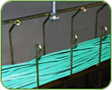
Center supported cable trays
Today, another type of cable tray is available for cable support and management. These systems (Figure E) are manufactured from aluminum and steel, with aluminum again being the material of choice. The advantages of these types of cable tray are installation speed and maximum cable freedom. These systems were generated to allow installers to side fill the cables, eliminating the stresses of pulling cables. They install using a variety of connectors and couplings, as opposed to pre-manufactured fittings. This adds to the installation speed and simplicity. The applications of these systems are primarily to support datacom cabling systems.
The rungs pass through the center spine at the bottom, as shown in (Figure E), or through the top, as shown in (Figure F).
Both top or bottom mount systems allow the installer to lay cable in from the sides as opposed to pulling cables through trapeze type supports.
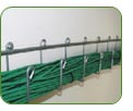
As not all installations or customer needs are the same, more specialized systems have developed. Wall-mounted racks are available (Figure G)
as well as multi-tiered systems (Figure H).
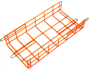
Wire basket systems
The newest cable support systems to hit our shores are wire basket systems (Figure I).
These systems are created from a steel wire two-inch by four-inch mesh. Their strengths are their low profile, unmatched installation adaptability, simplicity of accessories, and distribution stockable characteristics. Of the variety of finishes available, zinc plated is the most commonly used. These systems are not new to the world systems, as they are commonly used in Europe.
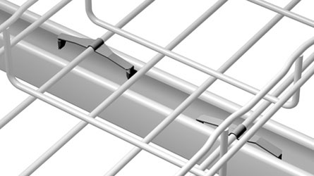
The 2x4 wire mesh construction (Figure J) offers some desired advantages not at first visible.
By cutting and removing segments of this system, it can be reformed and changed into "fittings" (Figure K). Installers will find these wire basket systems the most on-site adaptable of all the systems.
The wire baskets are being used primarily in the telecom sector of the market. As the acceptance increases and as distribution stock becomes more common, these systems can become an important part of the continuing cable tray evolution.
Cable tray today is ever changing, ever growing. It is doing what it should; it is evolving to satisfy a constantly changing set of customer needs. All of these systems have their strengths, all have their weaknesses. They are a growing part of the cable support products today and will continue to adapt and grow.
Standards
Standards affecting the two-side rail product groupings are: the applying electrical code, NEMA VE-1 or FG-1, UL classification, and NEMA VE-2. The applying electrical code depends on your area. Should it be the National Electrical Code, Article 318 will be of major interest. This document addresses cable fill allowed for different product types, where it can and can’t be used, and the cable types it can support. The NEMA VE-1 and NEMA FG-1 standards address the manufacturing standards for metal (VE-1) and non-metallic (FG-1) systems. These publications contain the standards to which the National Electrical Manufacturers Association members manufacture their products. The NEMA VE-2 is a fairly new document created to be an installation guide.
At this time, there are no domestic standards that mention wire basket
systems. The system’s loading capabilities are being stated in
terms that the U.S. standards do not address. The loading is being determined
by continuous beam testing, and a specified deflection is the controlling
factor. This type of testing is common in Europe and is part of the
proposed IEC (International Electrotechnical Commission) cable tray
specification.
|


 NEW-
Snake Tray Raceway Systems
NEW-
Snake Tray Raceway Systems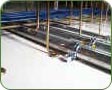


